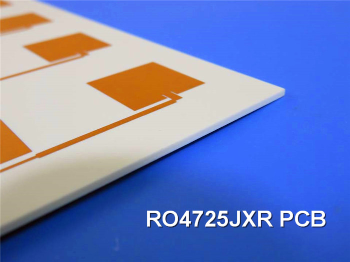
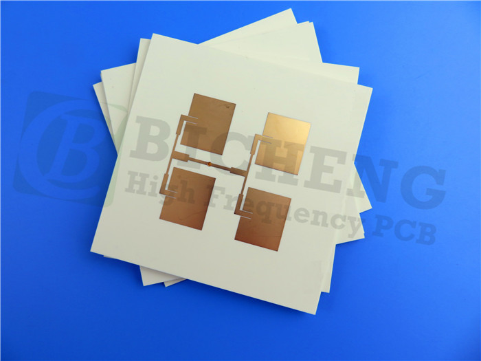
Rogers RO4725JXR High Frequency PCB - Antenna Grade RF PCB with DK 2.55 (30.7mil, 60.7mil)
(Printed Circuit Boards are custom-made products; the images and parameters shown are for reference only.)
General Description
The Rogers RO4725JXR High Frequency PCB is an antenna-grade circuit board designed for high-performance RF applications. Built on Rogers RO4725JXR laminates, this PCB offers a cost-effective alternative to traditional PTFE-based materials while maintaining excellent electrical and thermal properties. With a dielectric constant (Dk) of 2.55 ± 0.05, low Z-axis coefficient of thermal expansion (CTE) of 25.6 ppm/°C, and a dissipation factor ranging from 0.0022 to 0.0026, the RO4725JXR PCB ensures reliable performance in demanding environments. It is fully compatible with conventional FR-4 and high-temperature lead-free solder processes, making it easy to integrate into existing designs.
Features
1.Dielectric Constant (Dk): 2.55 ± 0.05 for consistent signal integrity.
2.Low Z-Axis CTE: 25.6 ppm/°C, ensuring reliable plated through holes.
3.Low TCDk (Thermal Coefficient of Dk): +34 ppm/°C, providing stable performance across temperature changes.
4.Low Dissipation Factor (Df): 0.0022 to 0.0026, minimizing signal loss.
5.High Glass Transition Temperature (Tg): Exceeds 280°C, ensuring thermal stability.
Benefits
1.Low Insertion Loss: Ensures minimal signal loss during transmission.
2.Dk Matched to PTFE-Based Materials: Facilitates seamless integration with existing designs.
3.Reduced Passive Intermodulation (PIM): Improves signal quality and reduces interference.
4.Consistent Circuit Performance: Provides reliable and predictable results for high-frequency applications.
Our PCB Capability (RO4725JXR)
| PCB Capability (RO4725JXR) | |
| PCB material: | Hydrocarbon / Ceramic / Woven Glass |
| Designation: | RO4725JXR |
| Dielectric constant: | 2.55 |
| Layer count: | Sinlge-sided PCB, Double-sided PCB, Multi-layer PCB, Hybrid PCB |
| Dielectric thickness: | 30.7mil(0.780mm), 60.7mil (1.542mm) |
| Copper weight: | 1oz (35µm), 2oz (70µm) |
| PCB size: | ≤400mm X 500mm |
| Solder mask: | Green, Black, Blue, Red, Yellow, White etc. |
| Surface finish: | Immersion gold, HASL, Immersion silver, Immersion tin, Bare copper, OSP, ENEPIG, Pure gold etc.. |
Typical Applications
Cellular Base Station Antennas
RO4725JXR Typical Properties
| Property | RO4725JXR | Direction | Units | Condition | Test Method |
| Dielectric Constant, εr Process | 2.55 ± 0.05 | Z | 10 GHz/23°C | IPC-TM-650 | |
| Dielectric Constant, εr Design | 2.64 | Z | 1.7 GHz - 5 GHz |
Differential Phase Length Method | |
| Dissipation Factor | 0.0026 | Z | 10 GHz/23°C | IPC-TM-650 | |
| 0.0022 | 2.5GHz | ||||
| Thermal Coefficient of εr | +34 | Z | ppm/°C | -50°C to 150°C | IPC-TM-650 |
| Volume Resistivity (0.030") | 2.16 X 10^8 | MΩ•cm | COND A | IPC-TM-650 | |
| Surface Resistivity (0.030") | 4.8 X 10^7 | MΩ | COND A | IPC-TM-650 | |
| PIM | -166 | dBc | 50 ohm 0.060” |
43dBm 1900MHz |
|
| Electrical Strength (0.030”) | 630 | Z | V/mil | IPC-TM-650 | |
| Flexural Strength MD | 121 (17.5) | MPa (kpsi) |
RT | ASTM D790 | |
| CMD | 92 (13.3) | ||||
| Dimensional Stability | <0.4 | X,Y | mm/m | after etch +E2/150°C |
IPC-TM-650, 2.4.39A |
| Coefficient of Thermal Expansion |
13.9 | X | ppm/°C | -55 TO 288°C | IPC-TM-650, 2.1.24 |
| 19.0 | Y | ||||
| 25.6 | Z | ||||
| Thermal Conductivity | 0.38 | Z | W/mK° | 50°C | ASTM D5470 |
| Moisture Absorption | 0.24% | % | 48/50 | IPC-TM-650 2.6.2.1 ASTM D570 | |
| Tg | >280 | °C | IPC-TM-650 2.4.24 | ||
| Td | 439 | °C | ASTM D3850 | ||
| Density | 1.27 | gm/cm3 | ASTM D792 | ||
| Copper Peel Strength | 8.5 | pli | 1 oz LoPro EDC | IPC-TM-650 2.4.8 | |
| Flammability | N/A | UL94 | |||
| Lead-Free Process Compatible | YES |